Updated: Nov 18, 2024
1. Introduction to DFMEA and Technical Risk Assessment
Objective:
- Identify potential failure modes for the energy device.
- Assess the severity, occurrence, and detectability of these failure modes.
- Develop mitigation strategies to reduce the likelihood of failures and their impact.
2. DFMEA Process
The DFMEA process consists of the following steps:
Step 1: Define the System/Device and Requirements
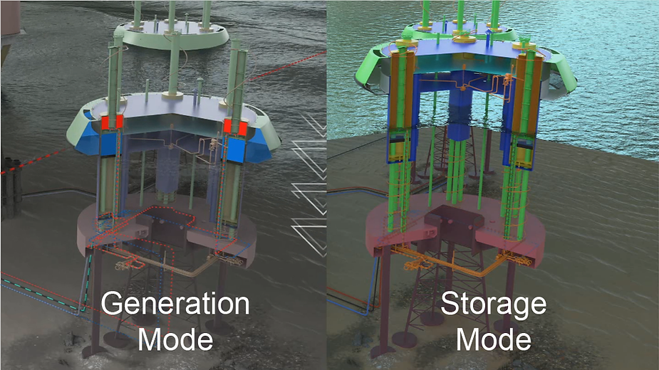
- System Overview: Energy device utilising wave energy or storage on demand.
- Primary Function: Capture and convert wave energy into usable electrical power (wave energy) or store and release energy for later use (gravitational energy storage system).
- Secondary Function: Provide reliable energy storage, manage charging/discharging cycles, and ensure system stability.
Step 2: Identify Potential Failure Modes
Each subsystem or component must be analysed for potential failure modes. For the energy device in question, failure modes could stem from both mechanical and electrical systems, as well as environmental factors.
1. Wave Energy Conversion System
Failure Mode 1: Structural failure of wave energy converters (WECs)
- Effect: Loss of energy capture efficiency, physical damage to the system.
- Potential Causes: Corrosion, fatigue from wave loading, material failure.
- Severity: High (due to system downtime and repair needs).
Failure Mode 2: Inaccurate wave tracking or positioning
- Effect: Reduced energy generation, system misalignment.
- Potential Causes: Sensor failure, control algorithm issues, mechanical misalignment.
- Severity: Moderate (energy capture is suboptimal, but the device may still function).
Failure Mode 3: Aging
- Effect: Reduced energy generation, increased friction and reduction of energy generation as a result of the limited ability to provide ideal weight in reciprocation.
- Potential Causes: Accumulation of biofouling in non-essential parts of the hull.
- Severity: Moderate (energy capture is suboptimal, but the device may still function).
2. Energy Storage System
Failure Mode 1: Accumulation of biofouling
- Effect: Increase in battery capacity but also increase in pressure for lifting purposes.
- Potential Causes: The accumulation of biofouling, as a result of aging or lack of maintenance increase the weight which has implications in generation mode. In storage mode the increase in weight results in an increase in storage because the ESWave is a gravitational energy device whose storage directly depends on the mass.
- Severity: Low.
Failure Mode 2: Inaccurate state-of-charge (SOC) estimation
- Effect: Energy imbalance, overcharge/undercharge, inefficient operation.
- Potential Causes: Faulty sensors, algorithm error.
- Severity: Moderate to High (depending on extent of imbalance).
Failure Mode 3: Hydraulics failure (e.g., solenoid valves)
The ESWave contains natural redundancies in some of the hydraulic valves but others are unique.
- Effect: Loss of power conversion, system shutdown.
- Potential Causes: Overvoltage, overcurrent, thermal stress, component aging.
- Severity: High (interrupts power flow).
3. Power Management and Control System
Failure Mode 1: Control system failure (e.g., loss of control or disoperation)
- Effect: Erratic system behaviour, damage to components, failure to optimise energy flow.
- Potential Causes: Software bugs, hardware failure, communication loss.
- Severity: High (system could become unstable or damage itself).
Failure Mode 2: Loss of communication or sensor malfunction
- Effect: Inability to properly monitor or adjust system performance.
- Potential Causes: Sensor drift, broken wiring, and faulty connections.
- Severity: Moderate (could result in suboptimal performance or incorrect readings).
Failure Mode 3: Hydraulic components malfunction
- Effect: Inability to properly operate or adjust system performance.
- Potential Causes: Valve stiffness, pneumatic membrane in pressure vessels, turbine blades damaged.
- Severity: Moderate (could result in suboptimal performance but it can also result of interruption in power flow). Some components in the TWEFDA Hub have a degree of redundancy, such as turbines and some valves, which means that, depending on the component the severity could vary.
4. Environmental Factors
Failure Mode 1: Saltwater corrosion of exposed parts
- Effect: Material degradation, structural failure.
- Potential Causes: Insufficient protective coatings, inadequate corrosion-resistant materials.
- Severity: High (system components could fail prematurely, leading to costly repairs).
Failure Mode 2: Extreme weather events (storms, high waves)
- Effect: Damage to infrastructure, misalignment, operational failures.
- Potential Causes: Inadequate design for environmental extremes.
- Severity: High (potential for complete system failure if not designed for worst-case conditions).
Failure Mode 3: Sea level rising
- Effect: Need to increase cylinder’s height
- Potential Causes: The planet is warming and ice sheets are thawing.
- Severity: High (The devices will need to be disconnected, towed to a shipyard and adapted to the new conditions).
Step 3: Risk Assessment (Severity, Occurrence, Detectability)
For each failure mode, assess the following:
- Severity (S): How severe is the consequence of the failure? (1 = minor, 10 = catastrophic)
- Occurrence (O): How likely is the failure to occur? (1 = unlikely, 10 = very likely)
- Detectability (D): How easily can the failure be detected before it causes harm? (1 = easy to detect, 10 = unlikely to detect)
Assessment:
Wave Energy Conversion System
| S | O | D | RPN | |
|---|---|---|---|---|
| Structural failure | 9 | 4 | 5 | 180 |
| Wave tracking or positioning | 5 | 4 | 2 | 40 |
| Aging | 6 | 9 | 2 | 108 |
Energy Storage System
| S | O | D | RPN | |
|---|---|---|---|---|
| Accumulation of biofouling | 1 | 5 | 6 | 30 |
| SOC estimation | 3 | 3 | 2 | 18 |
| Hydraulics failure | 9 | 6 | 4 | 216 |
Power Management and Control System
| S | O | D | RPN | |
|---|---|---|---|---|
| Control system | 7 | 6 | 4 | 168 |
| Communication/Sensors | 8 | 6 | 2 | 96 |
| Hydraulic components | 8 | 4 | 3 | 96 |
Environmental Factors
| S | O | D | RPN | |
|---|---|---|---|---|
| Saltwater corrosion | 7 | 9 | 3 | 189 |
| Extreme weather | 9 | 9 | 2 | 162 |
| Sea level rising | 9 | 2 | 2 | 36 |
Risk Priority Number (RPN):
RPN = Severity × Occurrence × Detectability
- Higher RPN values indicate higher priority failure modes that need more immediate attention.
Step 4: Develop Mitigation Strategies
For each high-priority failure mode (e.g., RPN > 150), propose actions to reduce risk.
1. Structural Failure of Wave Energy Converters
- Mitigation:
- Use corrosion-resistant materials, such as stainless steel or composite materials.
- Design for fatigue resistance, with regular inspections.
- Implement real-time monitoring of structural health (e.g., using strain gauges or vibration sensors).
2. Hydraulics Failure for Energy Storage
- Mitigation:
- Use reporting sensors.
- Increase preventative.
- Implement AI assisted predictive maintenance routines.
3. Control System Failure
- Mitigation:
- Implement fail-safe and backup control systems (e.g., secondary controllers, manual override).
- Robust software testing and error-handling protocols.
- Regular software updates and monitoring.
4. Saltwater Corrosion
- Mitigation:
- Regular maintenance and cleaning of exposed parts.
- Use anti-corrosion coatings or sacrificial anodes on critical components.
- Periodic inspection and replacement of affected parts.
5. Extreme Weather Events
- Mitigation:
- Design the system to withstand extreme weather conditions (storm surges, high waves).
- Implement dynamic positioning systems that allow the device to move in response to extreme conditions.
- Incorporate fail-safe mechanisms to shut down or reduce power output during unsafe conditions.
3. Conclusion:
This DFMEA outlines the potential failure modes, risks, and mitigation strategies for a wave energy or energy storage device at an early stage of development. The key areas of focus include mechanical integrity, energy storage reliability, control system robustness, and environmental resilience. By addressing these failure modes early in the design process, the device’s chances of successful deployment and long-term operation are significantly improved.
Additionally, the RPN values provide a priority ranking, helping to direct attention and resources to the most critical risk areas, ensuring that mitigation strategies are applied effectively.